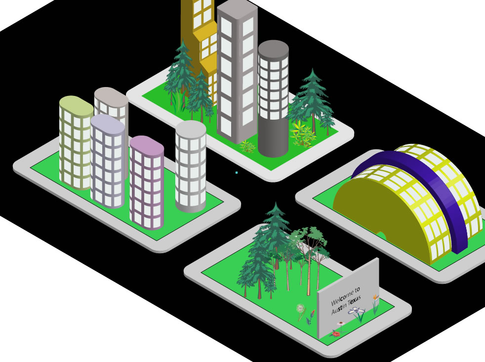
Creating An Isometric City
To make the process easier, Adobe Illustrator has built-in isometric views (angles). This will save a ton of time positioning objects on the stage.
TIP: Unlike Photoshop, where when you create certain objects (text, shape, etc.), they automatically create layers in the Layers panel, in Illustrator that is not the case. If you forget to create new layers, every objects you create will be placed in that SINGLE layer. While this may not be a problem for small project, it is best practice to create MULTIPLE layers to organize your content.
Create Concrete and Grass
- Create a new Web document and save it as Isometric City.
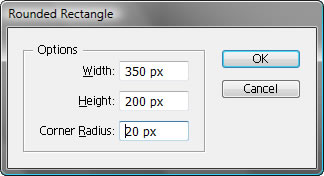
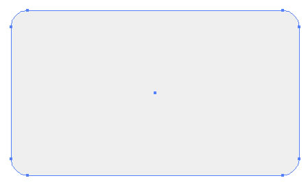
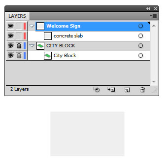
- Select the Rounded Rectangle tool and then click (without dragging) on the stage to create a rectangle with the following dimension (350w X 200h) with a radius of about 20 px and then click OK. Then, set the stroke to None and give it a light gray fill color (i.e., R:239 G:239 B:239 ) to represent the concrete.
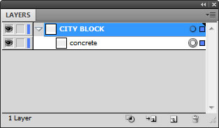
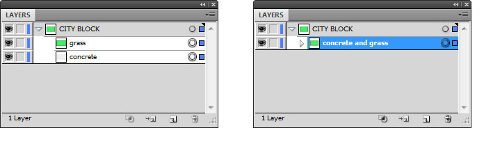
- Name the layer CITY BLOCK and its sublayer concrete in the Layers panel.
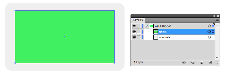
- Using the center point of the concrete layer as a guide, hold down the ALT key to draw a regular rectangle that cover most of the concrete to create the sidewalks. Set the fill to a "grass" green color. Name the layer grass.
- Lazzo the two sublayers (concrete and grass) with the selection tool and group them (CTRL+G) and rename the newly created <Group> sublayer concrete and grass or concrete and grass <Group>.
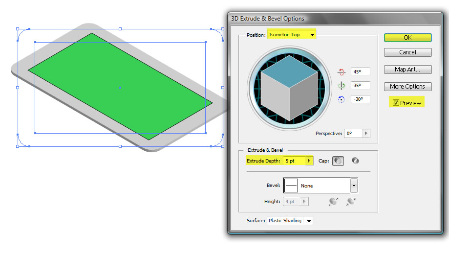
- Select the concrete and grass sublayer and select Effect > 3D > Extrude and Bevel. Check the Preview checkbox and the set the Position to Isometric Top and an Extrude Depth of 5 points and then click OK.
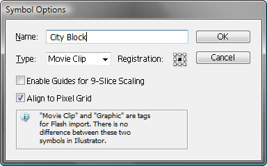
- Save this object as a symbol (F8) with a name of City Block so that it can be used to create the other City Blocks.
ALTERNATIVE: You can drag the sublayer to the Symbols panel to create a symbol
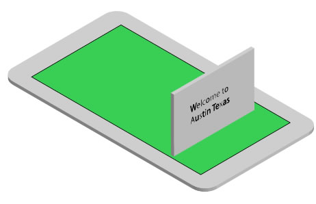
Create Welcome Sign
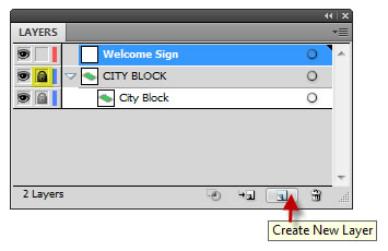
- Lock the City Block layer and the ALT + click on the new layer icon at the bottom of the Layers panel to create a new layer and name it WELCOME SIGN.
NOTE: You could have continue to include the Welcome Sign assets (i.e, slab, text, flower, trees,etc.) in the CITY BLOCK layer. However, because the welcome sign includes many objects, we decided to dedicate it to its own layer. We will move it into the CITY BLOCK layer later.
- Select the Rectangle tool and then click (without dragging) on the stage to create a rectangle with the following dimension (125w X 75h). Then, set the stroke to None and give it a light gray fill color (i.e., R:239 G:239 B:239 ) to represent the concrete slab. Name the sublayer from <Path> to concrete slab.
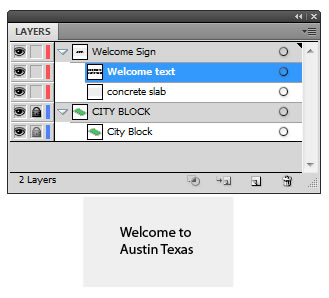
- Using the text tool, create some "welcome text" (i.e., Welcome to Austin, Texas). Format the text to your liking and name the layer welcome text and then move it to the center of the concrete slab.
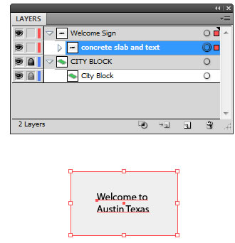
- Group the two sublayers (concrete slab and welcome) (CTRL+G) and rename the newly created <Group> sublayer Concrete slab AND text.
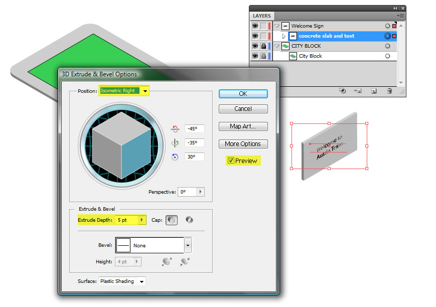
- Select the concrete slab AND text sublayer and select Effect > 3D > Extrude and Bevel. Check the Preview checkbox and the set the Position to Isometric Right and an Extrude Depth of 5 points and then click OK.
- Move the concrete slab and text to the City Block.
Create Flowers and Trees
- Using various symbol library items (Window > Symbols), draw several flowers and tree around and in back of Welcome sign.
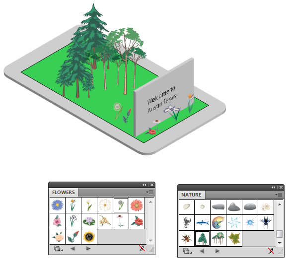
- Lock the Welcome sign layer and collapse its sublayers to make it more easier to see structure.
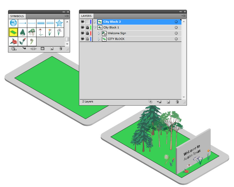
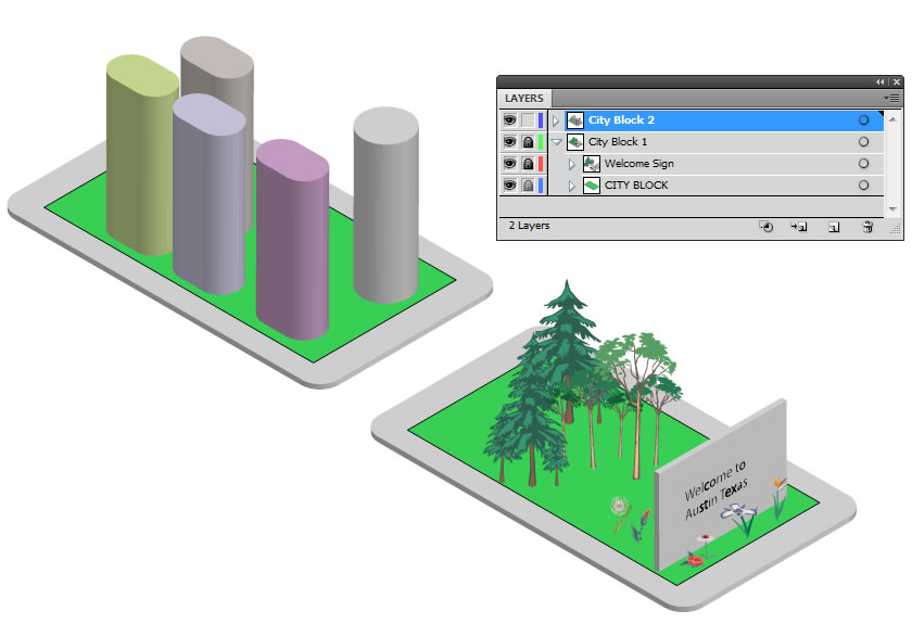
Create First City Block
- ALT+click on the new layer icon and name the layer City Block 1
- Drag and drop all of the other existing layers into this layer for better organization and maintenance.

Create Another City Block
- Lock City Block 1.
- ALT+click on the new layer icon and name the layer City Block 2.
- Drag and drop the city block symbol from the Symbols library.
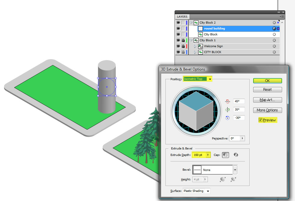
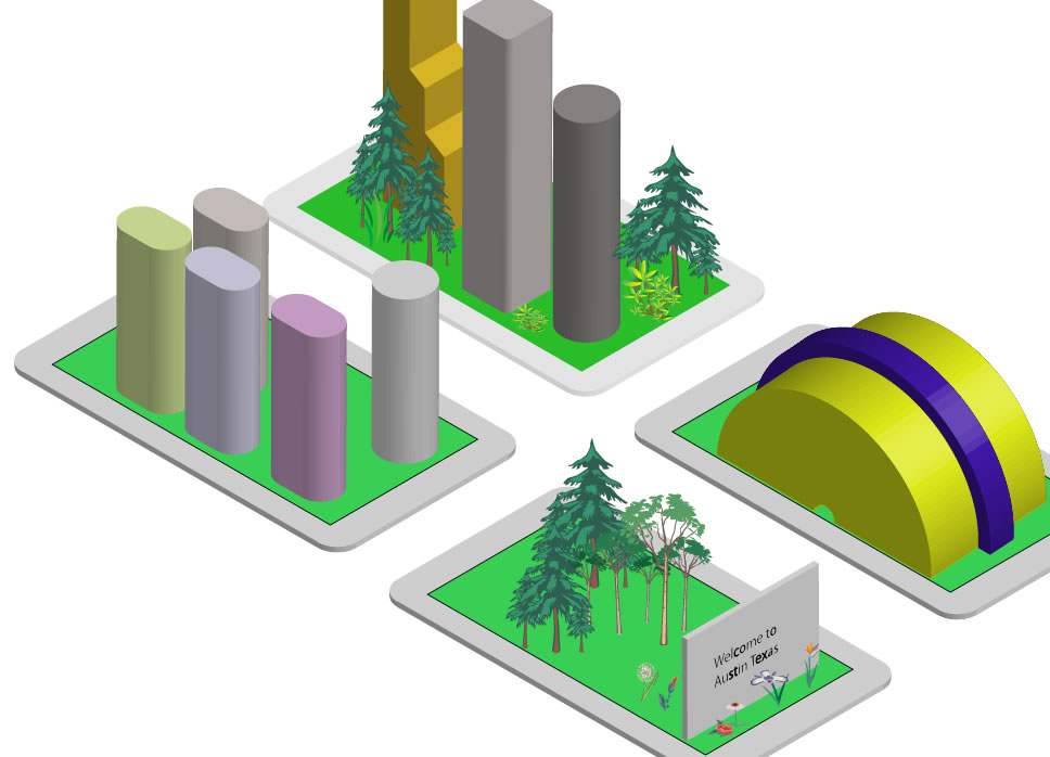
- Using the Ellipse tool, click (without dragging) on the stage to draw a circle with a height and width of 50 px. Fill the circle with a light gray color and no stroke. Then move the object on the city block.
- Name this layer round building.
- Select the building's sublayer and select Effect > 3D > Extrude and Bevel. Check the Preview checkbox and the set the Position to Isometric Top and an Extrude Depth of 150 points and then click OK.
- Repeat the previous three steps but this time use the rounded rectangular tool with a different color of gray. Duplicate the building 2 or 3 more times and position them in place as needed. You may have to use the Arrange menu to send a building forward or backward. Change the stoke color to change the color of a building is you want to. Name the layer round rectangle building.
TIP: You may only want to do ONLY one building and in the next section when you add windows, duplicate that building several times so that you don't have to "map" windows on each building individually. Then, you can also change the fill color to make each building look differently.
- Repeat steps 1-6 as many times as you like but this time use any custom shapes to make more City Blocks. You can also add trees, flowers or whatever else you want to include.
Create Windows for Buildings
- Using the rectangle tool, click to create a small box with a width and height of 15 px with a light gray fill and no stroke.
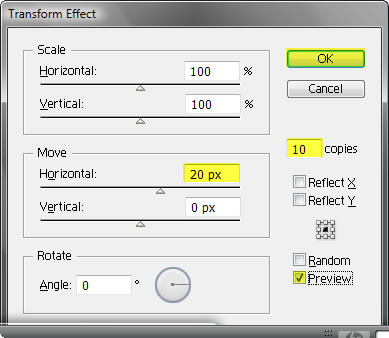
- With the box still selected, select the Effect > Distort & Transform > Transform.... Then, click on the preview button so you can see the transformation. Set the copies value to 10, set the Horizontal Move value to 10 and then click OK.
NOTE: This will make 10 copies of the window and position them 20 px from their center which will create spaces between them.
NOTE: You can not set both the Horizontal and Vertical Move at the same time otherwise, the objects (i.e., the windows) will be displayed diagonally. However, you can reapply the Transform effect again to copy the previous effect in another direction (i.e., vertically) as we will do next.
- With the box still selected, select the Effect > Distort & Transform > Transform... menu AGAIN. When it prompts you that another effect will be added to the existing effect, click OK.
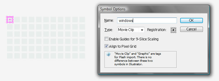
- In the Transform Effect dialog box, click on the preview box, set the Vertical Move value to 20 and set the copies value between 3 and 5 depending on your need and then click OK.
- Save the boxes as a symbol (F8) and give it a name of windows.
- Unlock all layers, and then apply the windows symbol to the buildings by clicking on the buildings INDIVIDUALLY and then opening the Appearance panel and click on the Extrude and Bevel link to open the 3D dialog box. Select the preview checkbox and then click the Map Art... button and then select one of the visible side of the building. Select the windows symbol from the drop down list and then resize and position the windows on the building interactively while you are transforming the symbol and seeing the building at the same time on the stage. Repeat this process for all visible sides of the building.
- (Bonus) Create a asphalt street by following the following steps:
- Create a new blank layer at the bottom of the Layer panel
- Set the fill color to black and the stroke to none.
- Select the regular rectangular tool and hold down the ALT key and draw a large rectangle from the center of the canvas to the outer edge of the canvas.
- Select Effect > 3D > Rotate and the select the Preview checkbox, set the Position type to Isometric Top and then click OK.
NOTE: Since we did not need to extrude the street, we decided to use the Rotate option instead of the Extrude option in the Effect menu.
NOTE: You could also add a filter to the street to make it look more like asphalt instead of a solid black fill.
Download Final Version